Industrial Furnace Temperature Measurement(PDF)
Industrial furnaces come in many shapes and sizes and are used across a wide variety of applications. As one would expect, monitoring the temperature of an industrial furnace is critical and is accomplished by measuring the temperature of the tubes inside the furnace. The two most common methods of measuring the temperature of the furnace tubes are: indirectly, by using infrared thermometers with line of sight to the tubes through a peek window; or directly, by placing
temperature elements in contact with the tubes themselves – this paper will be focusing on the latter. When measuring the tube temperature directly, most applications use tubeskin thermocouples. It is important to understand the design concepts inherent to tubeskin thermocouples and how those attributes optimize their performance in industrial furnace applications.
Feeding the Furnace
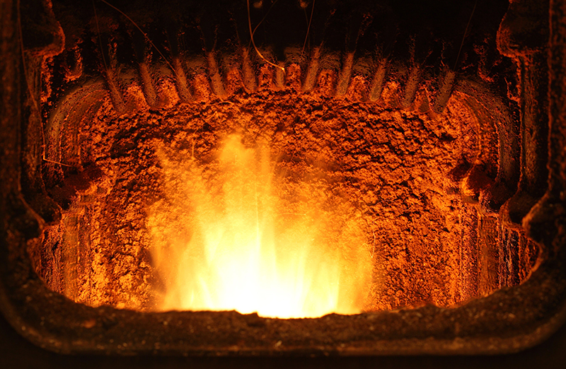
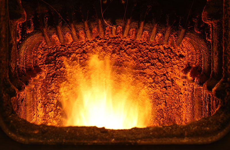
Inside an industrial furnace are series of tubes containing heat transfer fluid which is heated and then circulated throughout the plant and provides heat to various equipment such as heat exchangers. In the first part of the furnace, also known as the radiant section or firebox, the tubes are heated by direct radiation from the burner flame. Above the firebox is the convection section where the tubes are heated by convection for additional heat recovery. The temperature of the heat transfer fluid is determined indirectly by measuring the temperature at the surface of the tubes, on the side where the highest degree of heat transfer is occurring; this is commonly referred to as the “hot” side of the tube and the opposite face as transfer capability of the tubes degrades and eventually they will need to be replaced. This decline in heat transfer performance can be attributed to normal usage but can also be caused by scale buildup on the outside of the tubes and coke formation on the inside of the tubes. Under normal operating conditions, the high temperatures accelerate the 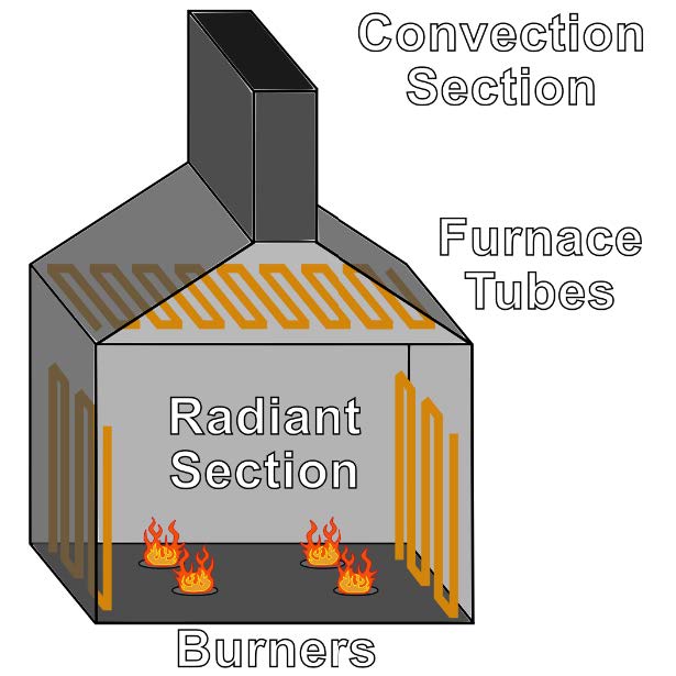 oxidation process inside the furnace which causes layers of soot and scale to buildup on the outside of the tube creating an insulative layer and reducing the heat transfer effectiveness from the furnace to the tubes. In a similar manner, coke buildup on the inside of the tubes negatively impacts heat transfer from the tubes to the fluid inside. When either of these insulating barriers form, the furnace overheats as it attempts to bring the tubes to the required temperature. This overheating damages the tubes and prematurely shortens their lifespan; however, coke and scale can be removed to extend the tube life. By using tubeskin thermocouples to measure the tube temperature, the furnace performance trending data provides early detection of overheating so that preventative measures can be taken.
Figure 1. Inside an Industrial Furnace
Tubeskin Traits
The construction of most tubeskin assemblies share some common traits. They typically use a type K thermocouple as it offers a higher temperature ceiling compared to RTDs or other thermocouple types. Although the sheath material will be different between applications, it must have a high temperature limit to withstand the intense heat it will continuously be subjected to. Likewise, the sheath material must have a high resistance to corrosion to protect against temperature-accelerated oxidation but also to withstand exposure to the flue gas, whose composition varies depending on the type of furnace. Tubeskin thermocouples also use heavy wall Mineral Insulated cable (MI cable) to limit degradation of the 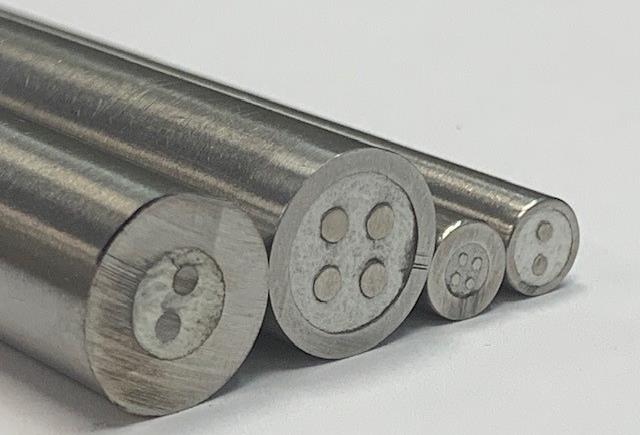 conductors inside and provide better durability. Further robustness is achieved by using thicker elements with larger conductors which have a longer life cycle in extremely harsh environments, though it comes at the cost of reduced flexibility.
Figure 2. Comparison of MI Cable Wall Thickness.
From Left to Right: 1/2” Heavy Wall, 1/2″ Standard Wall, 1/4″ Heavy Wall, 1/4″ Standard Wall
Achieving Optimal Accuracy
To obtain the most accurate temperature readings, the tubeskin thermocouple must measure the temperature directly at the surface of the furnace tube but without influence from the ambient temperature inside the furnace. This is accomplished by welding the tubeskin thermocouple directly to the furnace tube using a weld pad. Additionally, the tip of the thermocouple 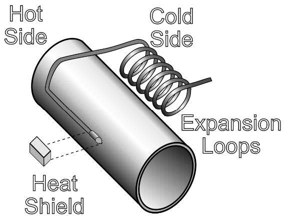 must land on the “hot” side of the tube where it is positioned closest to the flame; if it does not fall on the “hot” side, the measured temperature will be affected by the ambient conditions and the distance away from the flame. Even with the tip welded to the hot side of the tube, there are additional measures which can be taken to ensure the best accuracy. Since furnaces usually lack electrical interference/noise, tubeskin thermocouples use a grounded junction to provide direct surface contact for improved accuracy and faster response times. Another common practice is adding a heat shield to insulate the tip of the thermocouple from the ambient environment and isolate it to the tube’s surface.
Figure 3. Furnace Tube
Route to Success
The inside of industrial furnaces can be a complex maze with many twists and turns. After the thermocouple tip is welded to the tube, the remaining sheath length is taken back to the furnace wall, where it is held in a fixed position by the process connection. The path taken by the tubeskin from the tube back to the point of entry at the furnace wall is referred to as its routing. From the tip on the “hot” side of the tubes, the sheath is quickly routed back to the “cold” side of the tubes, so it stays protected from the flames on the “hot” side. After reaching the “cold” side of the tube the sheath often requires bends to be added in the field so it can be routed to the furnace wall. This is an important consideration one must keep in mind, as lack of additional sheath length for bending on the fly may make installation impossible or result in a suboptimal routing path. Moreover, if the tubeskin thermocouple is replacing an existing installation it cannot be welded at the same position, so additional sheath length may be needed to move it to a new position. As previously mentioned, tubeskin thermocouples use thicker elements to improve durability; however, complex furnace designs and routing may warrant using a smaller sized element to provide better flexibility and, thus, easier bending.
” This is an important consideration one must keep in mind, as lack of additional sheath length for bending on the fly may make installation impossible or result in a suboptimal routing path.”
Thrown for a Loop
 One of the most important features of tubeskin thermocouples are expansion loops or coils. As the furnace is cycling up fluctuations in temperature cause the tubes to move through expansion and contraction. Since the tubeskin thermocouple is kept in a fixed position by the weld on the tube and the fitting at the process connection, the movement can cause the tubeskin assembly to snap if there isn’t relief built into the design; this is where expansion loops come into play. Expansion loops are added by bending the sheath into tight concentric coils or other such shapes and are normally done by the tubeskin thermocouple manufacturer. When the tubes move the expansion loops act very similar to a spring and allow the coils to absorb the movement of the tube.
Figure 4. Tubeskin Thermocouple Assembly
Inside Out
The last consideration for tubeskin thermocouples in industrial furnaces is the installation process. Due to the large size of the expansion loops, they are unable to fit through the point of entry at the furnace wall; this makes it impossible to insert the tubeskin assembly from the outside into the furnace. In the same way, the fitting used to secure the tubeskin assembly at the process connection cannot be pre-mounted on the sheath. Therefore, the tubeskin thermocouple assemblies must be installed from the inside of the furnace and out through the furnace wall. The installation process starts by feeding the backend of the tubeskin assembly out through the point of entry on the furnace wall. The sheath inside the furnace is then bent as needed as it is routed to the “cold” side of the furnace tube from the tip, then the tip is welded in place on the “hot” side of the tube. If weld clips are being utilized to help secure the sheath in place, they are welded afterwards. Finally, the fitting is added onto the back end of the tubeskin assembly and affixed at the process connection.
As with most temperature sensors, there are many considerations when specifying a tubeskin thermocouple; because of the nature of their custom designs, it becomes even more critical to look through the entire design process from routing all the way to installation. A properly installed tubeskin thermocouple not only provides temperature readings, but trending which can be used to greatly extend the life and performance of furnace tubes saving both time and money. A basic understanding of tubeskin thermocouples and careful planning are key for successfully measuring temperature in an industrial furnace application.

Matthew Giunta – Marketing Manager SOR Controls Group
Matthew Giunta is a graduate of the University of Kansas with a Bachelor of Science in Chemical Engineering. Before coming to SOR Controls Group he worked as a Field Engineer cementing wells in the Permian Basin and as a Clinical Research Technician processing biological samples for investigational drug studies. Matthew is a Marketing Manager at SOR Controls Group and is responsible for overall product line management. He has also served as a Product Manager and an Inside Sales Engineer.
